In the previous day what we learned how to start a simple OpenGL ES project. Today we want to make it more interesting by actually drawing stuff. So, open project My Game in Android Studio and let us begin. If you do not know where to put code mentioned during this tutorial, don’t worry. I will provide downloadable source code for each day from this day forth.
Understanding primitives
Vertices, triangles, and primitives
You may find various objects in computer games with different shapes and characteristics. But regardless of how sophisticated objects are, they can all be described in the same way. In OpenGL ES (and in computer games in general), every object is defined by a series of “corners”. A triangle has 3 corners, a pentagon has 5 corners, and so on. One might argue that shapes like circles and spheres cannot be described in this way. The truth is that there are NO circles and spheres in a game world. In fact, there is nothing smooth. Even the smoothest spheres you may find in a game have corners, albeit many of them so they look smooth. As we are working in 2D, I give a 2D example to make this clear. Take a look at the following figure:

The left-most shape has unmistakably five corners. It does not even look like a circle. As we move to the right, we keep adding corners to this shape. The picture on the right seems to be a circle. However, quite frankly, it is only a polygon with only 50 corners. So, 50 corners is what it takes to convince you as the observer that this shape is a circle. In computer games it takes even less than this. You would be surprised how simple the polygons in games are sometimes. But, through some visual effects, material design, and game development tricks, you are almost convinced that they are those smooth real-world objects. When your focus is on your main character, you will not notice the grass under his feet is actually pictures painted on a number of rectangular shapes. So, in fact, everything in a game can be broken into those corners. Each of those corners are called a vertex.
Using a fixed group of vertices you are able to create numerous objects (not all of which meaningful) depending on how you connect them together. These objects are often referred to as meshes. These connections are described through triangles. A triangle is the simplest visible shape you can imagine in a 3D environment. Every mesh you see in a game is a collection of triangles. To make this more clear, the figure below shows a 3-dimensional “sphere” in several detail levels. You can easily notice the triangles that build them up.
The term “mesh” is often used in 3D context and we will not be using it after today. But in the coming days you might hear “primitives” a few times and that is what we are going to learn in the next subsection.
Primitive description
The definition of primitive is so broad that it is limited to the specific application you want to define it for. What we mean by primitive in this guide is simple shapes, such as triangles, rectangles, circles and lines. Our primitives are only made up of triangles. Anything more sophisticated (or with more edges) must be broken into triangles for us to be consider it a proper primitive. For example, a rectangle is made of two triangles, sharing an edge.
Every triangle is identified by its three vertices and that is the minimum information we require about it. In OpenGL, there is another piece of information we need to know, and that is the direction. A triangle is only visible from one side, and that is why you can see through some objects you sink into by mistake in a video game. Whether or not the triangle is facing you depends on how you define it. Take a look at the triangle below:

By convention, the triangle abc is facing you, but the triangle cba is facing away from you. Did you notice the difference here? The difference here was the order in which we read the vertices. By default, if the triangle reads counter-clockwise from where you are looking at it, OpenGL assumes it is facing you. With a little imagination, you realize that if you go to the other side of the above triangle, when you read abc, you will be traversing the vertices clockwise. This rule is not set on stone, and can be modified; OpenGL can be instructed to take clockwise triangles as facing the camera, but usually this default behavior is used.
Now we get to how we describe primitives to OpenGL. We know that we should introduce a list of triangles. There are several ways to do that, depending on our requirements.
Triangle list
This is the most basic method to describe primitives. Imagine we want to have the 2D primitive below:
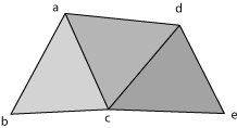
If we want to describe it as a triangle list, this is how we end up listing:
a, b, c, a, c, d, d, c, e
This method has a downside and that is high memory consumption. As you can see, we had to repeat vertices a, c, and d, because they were shared between triangles. For bigger primitives there will be more triangles sharing vertices and the repetitions will be significant. That is why other methods of listing triangles are usually preferred.
Triangle strip
Triangle strip is useful for when we have a strip of triangles, each sharing an edge with the previous one. You may think of many cases when the primitive can be broken down into triangle strips.
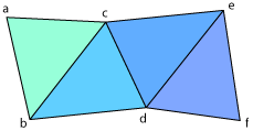
Using this method, the figure above will be defined as follows:
a, b, c, d, e, f
The first three items of the above list belong to the first triangle. But after introducing the first triangle, we only introduce new vertices, because we know we have a strip and the other two vertices are shared with the previous triangle. So after the first three items, each vertex adds a new triangle to our primitive description. By omitting repetition of vertices, this method saves memory.
Triangle fan
Sometimes triangle strips are not enough to fully describe an object. Examples are cylinders and spheres. For these cases there is another method of describing triangles. A triangle fan consists of a series of vertices with a common vertex.
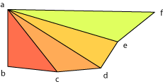
With this method, the figure above will be described as follows:
a, b, c, d, e, f
Vertex a marks the beginning of triangle fan. All consecutive vertices will be connected to a. Remember that triangle fans follow the orientation rules as triangles. So always make sure to list them counter-clockwise in the direction you want them to be facing.
Drawing using OpenGL ES
Getting started
If you remember the previous day, we didn’t touch the method onDrawFrame in our renderer. That’s what we are going to do today. But before that, we make a few small changes to the other methods. Previously we had two variables w and h in our onSurfaceChanged method. We are going to make these two variables private members of Stage and also introduce two new variables:
/* Stage width and height */
private float w, h;

/* Screen width and height */
private int screenWidth, screenHeight;
The difference between stage width/height and screen width/height is that the smallest of stage dimensions is always 600 and the other dimension is adjusted accordingly. Basically stage dimensions are screen dimensions scaled down or up based on the device’s resolution. Now remove the w and h declaration line from Stage and add the following code to onSurfaceChanged, right after you set w and h:
screenWidth = width;
screenHeight = height;
gl.glViewport(0, 0, screenWidth, screenHeight);
The last line above instructs that we are using the whole surface area to draw. Now bring onDrawFrame into view. Before we start rendering anything, we should clear the screen. As rendering happens frequently, it is a good idea to do so. Previously we set the clear color to opaque black (0, 0, 0, 1). Now we just need to clear using this color. So your onDrawFrame method starts with this code:
gl.glClear(GLES10.GL_COLOR_BUFFER_BIT);
Creating a primitive
Today we are going to draw a square. As we discussed before, a rectangle is a combination of two triangles. Take a look at the figure below. It shows how we represent a square of unit width centered at the origin using triangles.
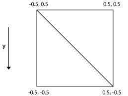
We use triangle strip method to draw this square. So, we should first go through the triangle cornered on the bottom-left and then add the top-right point to make the second triangle. So, if we define it as an array:
float vertices[] = {
  -0.5f, -0.5f,  0.0f,  // 0. left-bottom
   0.5f, -0.5f,  0.0f,  // 1. right-bottom
  -0.5f,  0.5f,  0.0f,  // 2. left-top
   0.5f,  0.5f,  0.0f   // 3. right-top
};
OpenGL ES understands this array. Each three components represent (x, y, z)-coordinates of a single vertex. As we are working in 2D we set the z component to zero. The array we made is called a vertex buffer, because it is a collection of numbers that represent vertices. A vertex buffer can virtually contain more than one primitive and each part of the array can be a different primitive. OpenGL supports offsetting over vertex buffers.
The next step is not so intuitive and in fact is not needed in the C version of OpenGL. OpenGL needs vertex buffers to be pure binary chunks of memory. A Java floating point array cannot be viewed as such. A C floating point array can, using a simple pointer cast. In Java instead, we must create a “float buffer” and fill it in using the the array. Create a private member of type FloatBuffer (from java.nio package) in Stage:
private FloatBuffer vertexBuffer;
Now add the code for our array in Stage constructor and below that add the following code (this essentially converts our managed vertex buffer to one accessible in native space):
ByteBuffer vbb = ByteBuffer.allocateDirect(vertices.length * 4);
vbb.order(ByteOrder.nativeOrder());
vertexBuffer = vbb.asFloatBuffer();
vertexBuffer.put(vertices);
vertexBuffer.position(0);
Matrices and transformations
Before we draw our square, we should apply some basic transformations to it:
- We have set the minimum dimension of our OpenGL ES context to 600 while our square is only one unit in width and height. So, we need to scale the square or else it would hardly be visible.
- We need to bring the square to the center of the screen.
Transformations of this sort in OpenGL are done through matrices. I don’t want to go too deep into the mathematics of this (however a small bit is inevitable), but what you should know about this is:
- The position (x, y, z) of any point is a vector v and can be multiplied by a matrix of the same dimension (3 by 3 in this case) such as M from the left: M v
- There is a matrix that, if multiplied by the position vector, results in scaling of the original vector by a certain factor. Similarly there are matrices that rotate or translate (move) the vector.
- All transformations are done with pivot at (0, 0, 0). For example if you multiply all vertices of a primitive by a rotation matrix, the primitive will rotate around the point (0, 0, 0) in space.
- Transformations are applied to the object from right to the left. If you multiply the vector by three transformation matrices, say L M N v, transformation N is applied first, then M on top of that, and then L is applied to the result of both.
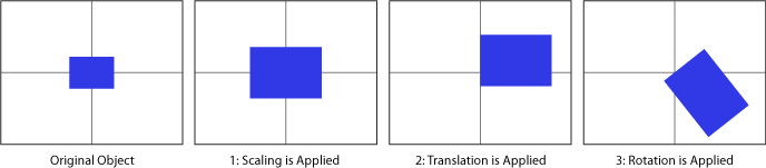
Moreover, OpenGL ES first multiplies all matrices in the order you ask them, and then applies the result to the drawing. This means that if you apply transforms in the following order:
- Rotate the matrix (call it R)
- Translate it to another point (call it T)
- Scale it with a factor (call it S)
The resulting matrix will be R T S which is then multiplied by v from the left. But according to what we said, transformations will take effect from right to left. So before drawing, the object will first be scaled, then moved to some new point, and then the result (wherever the object now is) will rotate around the origin. The figure below depicts this.
Long story short, transformation calls are always in the reverse order of their corresponding calls.
In our case, we need to scale and move the primitive. And we want scaling to be the first thing that applies. Because if the object is not centered at the origin when scaling, scaling causes it to move away from the origin. So we use the following code to achieve this:
gl.glPushMatrix();
gl.glTranslatef(w / 2, h / 2, 0);
gl.glScalef(120, 100, 0);

/* Rendering code goes here. */

gl.glPopMatrix();
In OpenGL, there is a stack of matrices for each matrix mode (by mode we mean view, projection, etc). glPushMatrix pushes the current matrix stack down by one and duplicates the top of the stack. The matrix in effect (both for modifications and for drawing) will always be the one on the top. glPopMatrix discards the top of the stack and moves back to the one right below it. The advantage of this stack-based scheme is that once we are done with a matrix, we just pop it out and we will revert back to the previous one.
For example, we have done two modifications to our matrix here. We first scale the square (non-uniformly) by 120 and 100. Then move it to the middle of the screen, which is w / 2 and h / 2. This works perfectly for the first frame. But if we don’t reset the matrix, the next frame will make the same changes to the result of the first frame, scaling the square again and moving it further off center. The next frame will do the same and after a frame or two, the square will be completely out of view and all you will see is going to be a black screen (the clear color). We could undo all the changes by applying their complement transforms in the reverse order. But with the stack structure of OpenGL ES, we just pop the matrix and we are good to go for the next frame.
Drawing the primitive
Now that we have our vertex buffer stored properly in the private field vertexBuffer and matrices are set, it is time to bring it into the screen. Our vertex buffer has exactly four vertices and consists of a single primitive. We just need to instruct all this to OpenGL ES:
gl.glVertexPointer(3, GL10.GL_FLOAT, 0, vertexBuffer);
gl.glDrawArrays(GL10.GL_TRIANGLE_STRIP, 0, 4);
The method glVertexPointer introduces vertexBuffer as the current working vertex buffer. The first argument is the number of components per vertex and second argument is the type of each component. The method glDrawArrays is used to draw vertices off vertex buffers. For the first argument, we tell it the method we have stored our primitive in the buffer. We specified GL_TRIANGLE_STRIP as we have used triangle strip method. The next argument is the index of the first vertex we want to draw off the array. We’d like to start from the beginning, so we provided 0. Finally, the last argument is the number of vertices we want to read from the array. Again, we want to read it all, so we plug 4 into this argument. The complete code for onDrawFrame becomes like this:
public final void onDrawFrame(GL10 gl) {
	gl.glPushMatrix();
	gl.glClear(GLES10.GL_COLOR_BUFFER_BIT);
	gl.glTranslatef(w / 2, h / 2, 0);
	gl.glScalef(120, 100, 0);

	gl.glVertexPointer(3, GL10.GL_FLOAT, 0, vertexBuffer);
	gl.glDrawArrays(GL10.GL_TRIANGLE_STRIP, 0, 4);
	gl.glPopMatrix();
}
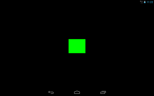
You may now run the app. The result may not be so astonishing. It’s simply a white box in the middle of a black screen. To give it some more spice you can give it a color (before calling glDrawArrays):
gl.glColor4f(0, 1, 0, 1);
This method takes four arguments: red, green, blue, and alpha values of your color. If you are a Photoshop user, you’d expect them to be in the range 0..255. But in OpenGL, they are in the range 0..1. So, the color specified above is #00FF00. You can see the result below on a Nexus 7 emulator:
Next step
Today’s work might seem a little off topic as far as our game engine is concerned. But don’t worry. We are perfectly on the right track. We are building knowledge as well as a game engine and that’s why some days might be tedious and somehow diverge from the main topic. The plan for next day is to talk about textures and start thinking about our texture manager. Be with Game Development Days on our journey towards a home-made game engine. Below you can download the full source code for Stage as of now: